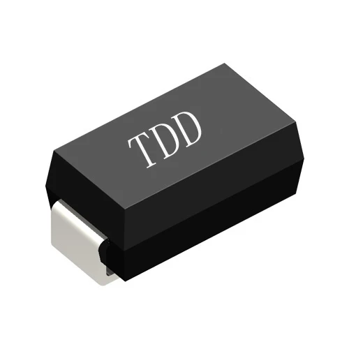
This guide compares high efficiency rectifier diodes with standard silicon diodes, explaining conduction-loss calculations, thermal trade-offs, price, and selection for real power-supply scenarios.
Home-Resource-Blog-Conduction Losses: High-Efficiency vs Standard Rectifier Diodes
Conduction Losses: High-Efficiency vs Standard Rectifier Diodes
Nov.03,2026
Share:
When a power supply runs hot or has to meet a tighter efficiency target, choosing between a High Efficiency Rectifier Diode and a standard rectifier diode can affect both heat and operating cost. The high efficiency rectifier diode vs standard diode decision depends on more than a headline forward-voltage figure: rectifier diode conduction loss calculation, low forward voltage diode for power supply selection, bridge rectifier efficiency, forward voltage drop, thermal management, Vf, average forward current, and junction temperature all matter. The right comparison starts with the circuit’s actual current waveform and operating temperature.
A rectifier conducts current in one direction and blocks it in the other. While it conducts, the diode dissipates power primarily through its forward voltage drop. For a simplified DC circuit, a useful first estimate is Pcond ≈ VF × IF. In a real rectifier, current varies over time, so a more accurate calculation is the average of the instantaneous product vF(t)iF(t) over a cycle. This distinction matters in bridge rectifiers with capacitor-input filters, where current arrives in narrow pulses rather than as a smooth waveform.
“High efficiency” is not one diode technology. The label may describe a Schottky diode with a relatively low forward drop, an ultrafast silicon diode designed to reduce reverse-recovery loss, or a silicon-carbide (SiC) diode suited to high-voltage switching applications. A conventional silicon PN rectifier may have a higher forward drop than a comparable low-voltage Schottky part, but it can offer lower reverse leakage or a more favorable cost at a given voltage and current rating. Compare the datasheet curves at the intended current and temperature, not just the product name.
High Efficiency Rectifier Diode vs Standard Diode: What Changes Conduction Loss?
As a broad guide, standard silicon PN rectifiers often show a forward drop around 0.7–1.1 V at specified operating currents. Many Schottky rectifiers fall around 0.3–0.6 V under suitable low- or medium-voltage conditions. These are indicative ranges, not guaranteed values: the actual Vf depends on current, junction temperature, die size, and rated voltage. Some high-voltage Schottky parts have higher drops, and an ultrafast PN diode may be chosen for its reverse-recovery behavior rather than for a lower Vf.
Reverse recovery is the brief period after a conducting diode is switched off while stored charge is removed. In high-frequency converters, reverse-recovery charge (Qrr) can add switching loss and electrical noise. A Schottky diode generally has no minority-carrier reverse-recovery charge in the same sense as a PN diode, although its junction capacitance and leakage still matter. SiC diodes are valued in high-voltage, high-frequency designs for their switching characteristics, but they are not automatically the lowest-loss or lowest-cost choice at every operating point.
High Efficiency Rectifier Diode Forward-Voltage and Recovery Trade-Offs
The following comparison is a screening guide. Confirm all limits, curves, and thermal ratings in the exact manufacturer datasheet before substitution.
Parameter
Standard silicon PN rectifier
High-efficiency Schottky rectifier
High-efficiency ultrafast or SiC rectifier
Typical forward-drop tendency
Often about 0.7–1.1 V at relevant rated currents
Often lower in suitable low-voltage applications; roughly 0.3–0.6 V is a broad guide
Varies by technology and rating; do not assume it is lower than standard PN
Reverse-recovery behavior
Can be relatively slow; check trr and Qrr
No PN-style minority-carrier recovery, but junction capacitance and leakage remain
Ultrafast PN reduces recovery time; SiC typically has low reverse-recovery charge
Reverse-voltage suitability
Available across a broad range of ratings
Often strongest in lower-voltage applications; verify voltage rating and margin
Ultrafast silicon and SiC options serve higher-voltage switching designs
Leakage and temperature
Often modest leakage, depending on device and temperature
Reverse leakage can rise substantially with temperature in some parts
Device-specific; evaluate maximum leakage at the hottest expected junction
Typical design priority
Cost, availability, and straightforward rectification
Lower conduction loss in appropriate low-voltage circuits
Reduced switching loss in demanding high-frequency or high-voltage circuits
Key selection check
Vf, IF(AV), surge rating, thermal resistance
Vf, VRRM, leakage, temperature, surge rating
Vf, Qrr or recovery behavior, VRRM, switching conditions, thermal limits
High Efficiency Rectifier Diode Parameter Comparison
Consider a bridge rectifier delivering a steady 5 A load. Two diodes conduct in series during each half-cycle. If the operating forward drop is 0.9 V per diode for the standard-diode option, the simplified conduction estimate is 2 × 0.9 V × 5 A = 9 W. If a suitable high-efficiency alternative measures 0.45 V per diode at the same current and temperature, the estimate is 2 × 0.45 V × 5 A = 4.5 W. The difference is 4.5 W, or 50% of the estimated diode conduction loss in this example.
This is an illustrative calculation, not a universal product comparison. In a capacitor-input supply, the bridge current is pulsed, and the diode’s average current is not necessarily equal to the DC load current. Use measured or simulated diode waveforms and calculate the average of vF(t)iF(t) for each device. Include transformer resistance, wiring, switching loss, and any changes in output voltage when comparing complete systems.
Heat follows the loss. A 4.5 W reduction can ease heatsink requirements or lower the local temperature, but the resulting junction temperature depends on the package, PCB copper, airflow, mounting, and thermal resistances. Estimate it using the appropriate thermal path—for example, TJ ≈ TA + PDRθJA when that junction-to-ambient model matches the assembly—and verify the result in the finished product. A diode that has a low room-temperature Vf but excessive hot leakage may not deliver the expected efficiency at elevated temperature.
High Efficiency Rectifier Diode Conduction-Loss Calculation
To make the calculation practical, imagine a small 5 A DC supply whose bridge runs warm during continuous operation. A technician can record the voltage across each conducting diode and the current waveform after the supply reaches thermal equilibrium. If the measured operating drop is close to the illustrative 0.9 V per diode, the bridge’s conduction loss may be near the 9 W estimate under a smooth-current assumption. The technician then tests a candidate replacement at the same load, input voltage, and temperature, while checking reverse-voltage margin, surge current, and output regulation.
This is an engineering example, not a claimed customer testimonial or a report of independently verified field data. It shows why a datasheet-only swap can mislead: changing diode technology can also change leakage, recovery behavior, stress during startup, and thermal balance. A safe evaluation records the original and replacement waveforms and temperatures under identical conditions.
High Efficiency Rectifier Diode Example: A Bench-Check Scenario
For a low-voltage DC supply, battery-powered equipment, or a secondary-side rectifier where diode drop is a meaningful share of the output voltage, a suitable Schottky diode can reduce conduction loss. Confirm its reverse-voltage rating, surge capability, and hot leakage. For a mains-frequency rectifier where the switching frequency is low and the bridge is not a major source of heat, a standard PN diode may be a cost-effective choice. In a high-frequency converter, an ultrafast or SiC diode may be justified when lower recovery-related switching loss improves the full converter’s performance.
Price should be compared at the same voltage class, current rating, package, qualification level, and supply volume. Standard rectifiers are often inexpensive and widely available. High-efficiency Schottky, ultrafast, and SiC options can carry a higher unit price, with the premium varying by specification and sourcing conditions. Avoid assuming a fixed percentage premium: request a current quotation for the exact part and quantity, and include heatsink, PCB, assembly, and energy costs in the comparison.
For a continuously operating product, the example’s 4.5 W saving would equal 39.42 kWh over 8,760 hours if the measured saving remained constant all year. At an assumed electricity rate of $0.15 per kWh, that is about $5.91 per unit annually. This estimate excludes changes in system efficiency, duty cycle, cooling, and energy prices. For intermittent equipment, the annual saving may be much smaller, so the diode premium may not pay back through electricity savings alone.
High Efficiency Rectifier Diode Scenario and Price Comparison
There is no single, verified user rating that fairly represents every diode family or application, so this comparison does not invent customer quotations. In practical design reviews, engineers commonly judge a rectifier by whether it meets its thermal limit, survives startup and surge conditions, maintains the required output, and remains available at an acceptable cost. A low Vf reading is useful, but it is not a substitute for checking hot leakage, reverse-voltage margin, and long-term operating conditions.
When evaluating suppliers, ask for traceable datasheets, lot identification, availability, and support for selecting a device against your circuit conditions. Shenzhen Daya Electronics Co., Ltd. can be included in a supplier comparison alongside other manufacturers and distributors; evaluate its proposed part using the same technical and commercial checklist rather than relying on a brand name alone. Confirm the exact ordering code and obtain written specifications before qualification.
High Efficiency Rectifier Diode User Feedback and Evaluation
How to Choose a High Efficiency Rectifier Diode Without Overbuying
A balanced selection process is more reliable than choosing the part with the lowest advertised forward drop. First, identify the maximum repetitive reverse voltage and include the required transient margin. Next, determine the actual average, RMS, and peak forward current from the circuit waveform. Then compare Vf at the expected current and junction temperature, along with reverse leakage, surge current, recovery charge, package thermal resistance, and operating frequency. Finally, test the candidate in the assembled product at minimum and maximum input, full load, startup, and the hottest expected ambient condition.
High Efficiency Rectifier Diode Selection by Application
Choose a standard silicon rectifier when the circuit is low-frequency, heat is manageable, and initial component cost and broad availability matter more than a small efficiency gain.
Consider a Schottky rectifier when the voltage rating and temperature behavior fit the design and a lower forward drop can materially reduce loss, especially in low-voltage circuits.
Consider an ultrafast or SiC diode when switching frequency, reverse-recovery loss, voltage rating, or converter behavior justifies the additional evaluation and cost.
Do not select by Vf alone when reverse leakage, hot operation, surge events, or safety margins could dominate reliability or total loss.
For a first-pass decision, rank candidate parts by measured loss in the actual circuit, then compare total cost of ownership. If the diode is barely warm and runs only occasionally, a premium part may offer little practical benefit. If the rectifier operates continuously and contributes several watts of heat, a qualified lower-loss replacement may reduce cooling needs or improve system efficiency—provided the replacement meets every electrical and thermal limit.
High Efficiency Rectifier Diode Summary and Next Step
A high efficiency rectifier diode is most suitable when its lower measured conduction or switching loss solves a real thermal or efficiency problem. A standard diode is often the sensible choice when its loss is acceptable and lower cost, availability, or operating margin matters more. Before ordering, compare the high efficiency rectifier diode vs standard diode using rectifier diode conduction loss calculation and the complete operating waveform; verify the low forward voltage diode for power supply choice against bridge rectifier efficiency, forward voltage drop, thermal management, Vf, average forward current, and junction temperature. Share your circuit voltage, current waveform, switching frequency, ambient temperature, and quantity with Shenzhen Daya Electronics Co., Ltd. or another qualified supplier, then request exact-part datasheets and test samples for an unbiased bench comparison.
The rectifier diode is a semiconductor device based on the unidirectional conductivity of the PN junction. Its main function is to convert alternating current energy into direct current energy.