Choosing a Small Signal Schottky Diode is not simply a matter of finding the lowest forward voltage or the lowest reverse leakage current. These parameters pull circuit performance in different directions, and the right balance depends on the circuit, operating temperature, battery budget, and purchasing requirements. This guide explains how to compare parts fairly, what to verify in datasheets, and how to reduce design and sourcing risks.
Engineers and purchasing teams commonly need answers to practical questions: Will a lower forward voltage extend battery life? Could reverse leakage drain a battery while the device is idle? Are datasheet values comparable when test conditions differ? The sections below address these concerns with a parameter comparison, application guidance, and a qualification checklist.
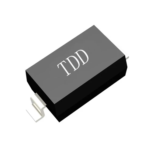
Understand the tradeoff before comparing diode specifications
Forward voltage reduces conduction loss, while reverse leakage adds standby loss
Forward voltage, usually written as Vf, is the voltage drop across the diode when it conducts. In a battery-powered circuit, a lower Vf can leave more voltage available to the load and reduce power dissipated in the diode. The benefit depends on forward current: Vf is not a fixed value, so compare it at the current your circuit actually uses.
Reverse leakage current, usually written as Ir, flows when the diode is reverse biased. It is often small, but it can matter in circuits that remain connected to a battery for long periods, especially when the rest of the system is in a low-power sleep state. Leakage generally rises with temperature, so a room-temperature value alone may not predict worst-case battery drain.
- Prioritize Vf when the diode conducts often or carries meaningful current.
- Prioritize Ir when the circuit spends most of its life reverse biased or idle.
- Check both values at the relevant current, reverse voltage, and temperature.
Use the circuit duty cycle to judge which loss matters most
A diode in a frequently active signal path may spend little time reverse biased, making its forward drop the more visible loss. A diode in a battery isolation or protection path may remain reverse biased for weeks, making leakage more important than a small difference in Vf. For mixed operating modes, estimate both losses across the full duty cycle rather than selecting from one headline specification.
Compare core parameters under matching test conditions
Use a parameter table to screen candidates consistently
The comparison below is a selection framework, not a claim that every device has the same limits. Exact ratings vary by part number and package. Record the datasheet conditions beside every value before ranking candidates.
| Parameter | What to compare | Why it matters | Purchasing or design check |
|---|
| Forward voltage, Vf | Value at the circuit forward current and relevant temperature | A lower drop can reduce conduction loss and preserve load voltage | Do not compare values measured at different forward currents |
| Reverse leakage, Ir | Value at the expected reverse voltage, at room and elevated temperature | Leakage can reduce standby life and shift high-impedance circuit levels | Check maximum limits as well as typical values |
| Reverse voltage rating | Maximum repetitive reverse voltage and circuit transients | Insufficient margin can cause excess leakage or device failure | Include supply tolerance, ringing, and protection behavior |
| Forward current rating | Continuous and peak current under the intended thermal conditions | Excess current raises temperature and can change performance | Check derating, pulse duration, and PCB heat dissipation |
| Junction capacitance | Capacitance at the stated reverse voltage and frequency | Capacitance can affect switching speed and RF or high-impedance signals | Compare at similar bias and frequency conditions |
| Operating temperature | Ambient and junction temperature limits | Temperature affects leakage, reliability, and available current | Confirm the full product environment, not just typical laboratory use |
| Package and qualification | Footprint, assembly compatibility, and required compliance | Package changes can affect production yield and thermal behavior | Confirm lifecycle status, traceability, and supply continuity |
Typical values and maximum values answer different questions
A typical Vf or Ir value can help estimate normal operation, but it is not a production guarantee for every unit. Maximum ratings and guaranteed limits are more useful for worst-case design and purchasing approval. For a battery product, calculate standby current with a conservative leakage figure at the highest expected temperature, then verify the result on assembled hardware.
Datasheets may specify leakage at different reverse voltages and temperatures. A candidate with a smaller published Ir number is not automatically better if that number was measured under a less demanding condition. Normalize the test conditions before comparing parts.
Estimate battery life using real operating modes
Separate active current from standby leakage
Battery life depends on the complete circuit, not one diode specification. Estimate the diode contribution by multiplying forward voltage by forward current during conduction, and by adding reverse leakage to the standby current budget when the diode is reverse biased. Then account for the time spent in each mode.
- List active, sleep, and fully idle operating states.
- Record diode current, bias direction, and duration for each state.
- Use datasheet maximum leakage at the expected worst-case temperature for a conservative estimate.
- Include leakage from other components, battery self-discharge, and measurement uncertainty.
- Measure sleep current on the finished board and compare it with the budget.
Treat battery-life improvement as a testable outcome
Reducing Vf can improve efficiency when the diode carries current regularly, but it may have little effect if conduction is brief. Reducing Ir can be more valuable in long standby periods, but the benefit depends on how much of the total sleep current the diode contributes. Compare candidate parts in the same board and operating profile; do not infer a specific number of extra battery hours from a datasheet value alone.
Evaluate stability across temperature, voltage, and production variation
Check leakage at the hottest operating condition
Reverse leakage is temperature sensitive and can increase substantially as junction temperature rises. This can affect battery drain and, in high-impedance circuits, signal levels or bias points. Review temperature curves when provided, and test at the highest realistic board temperature rather than relying only on a room-temperature reading.
Check circuit margin during startup and transients
Startup current, supply variation, and switching transients can push a diode beyond the conditions used in a simple steady-state calculation. Confirm reverse-voltage headroom, peak forward current, and power dissipation. If the diode protects a sensitive input or steers signals, test the actual waveform and confirm that leakage and capacitance do not disturb circuit operation.
- Test at minimum and maximum supply voltage.
- Test at the product temperature extremes.
- Measure standby current after the circuit has settled.
- Check signal integrity and startup behavior on the final PCB layout.
Match the diode choice to the application
Low forward voltage is often preferred in frequently conducting paths
For a power path, rectifier function, or frequently active battery circuit, lower Vf can reduce conduction loss and voltage drop. Confirm that the candidate also meets current, reverse-voltage, thermal, and package requirements. This approach is appropriate when the diode conducts often enough for forward loss to be a meaningful part of the energy budget.
Low leakage is often preferred in long-standby battery products
For a battery-powered sensor, memory backup path, or circuit that remains idle for long periods, low Ir may be the more important criterion. Verify maximum leakage at elevated temperature and the actual reverse voltage. A low-leakage choice is most useful when diode leakage is a significant portion of the total standby current.
Low capacitance matters in fast or high-impedance signal paths
In RF, fast switching, and high-impedance circuits, junction capacitance can affect signal shape or response time. In these applications, Vf and Ir remain relevant, but they are not the only selection criteria. Compare capacitance under matching conditions and validate performance in the final circuit.
Compare advantages and disadvantages before approving a part
Balance performance benefits against design and sourcing risk
- Lower Vf can reduce conduction loss, but it does not guarantee longer battery life if the diode rarely conducts.
- Lower Ir can reduce standby drain, but leakage may rise at higher temperatures.
- A higher reverse-voltage margin can improve robustness, but may involve a different balance of Vf, leakage, capacitance, package, or cost.
- A small package can save board space, but thermal limits and assembly capability still need review.
- A low-cost candidate can meet electrical targets, but lifecycle status, traceability, and supply consistency affect production risk.
Use a weighted comparison rather than a single-number ranking
Score each candidate against the actual application priorities. For example, a long-standby product can assign more weight to maximum Ir at high temperature, while a frequently conducting path can assign more weight to Vf at its operating current. Keep hard requirements such as reverse-voltage rating and package compatibility as pass-or-fail checks rather than allowing a strong score in one area to hide a critical failure in another.
Use a qualification checklist to reduce purchasing problems
Confirm datasheet conditions, samples, and production details
- Request the full datasheet and confirm the exact part number and package.
- Compare Vf and Ir using the same current, reverse voltage, and temperature conditions.
- Check guaranteed maximum values, temperature range, capacitance, and current ratings.
- Confirm manufacturing status, lot traceability, compliance needs, and expected lead time.
- Test representative samples in the target circuit, including temperature and standby measurements.
- Define approved alternates only after checking electrical behavior and PCB compatibility.
Ask suppliers for evidence that supports the application
Purchasing teams should request current datasheets and clarify whether quoted values are typical or guaranteed. For high-volume or long-life products, also confirm change-notification practices, lot documentation, and the availability of production support. Shenzhen Daya Electronics Co., Ltd. can be included in the supplier review process when buyers are comparing Small Signal Schottky Diode options and need to discuss application requirements and sourcing information.
Choose by operating profile, then verify on the finished board
Apply the selection rule that fits the product
- Choose a low-Vf direction when frequent forward conduction dominates energy loss.
- Choose a low-Ir direction when long reverse-biased standby dominates battery drain.
- Prioritize voltage margin, temperature behavior, and capacitance when reliability or signal integrity is critical.
- Use matched-condition data and board-level tests before approving a production substitute.
The best Small Signal Schottky Diode is the one that meets the circuit's worst-case requirements while balancing forward loss, leakage, temperature behavior, package fit, and supply needs. Shenzhen Daya Electronics Co., Ltd. can support supplier discussions as purchasing teams compare parts, but the final choice should be confirmed against the applicable datasheet and measured in the intended design.


