Choosing a General Rectifier Diode starts with understanding how much of the AC waveform a circuit converts into DC. Half-wave rectification is simple and low cost, while full-wave rectification generally provides smoother, more usable output. The right choice depends on load current, ripple tolerance, transformer design, heat, and the demands of the equipment being powered.
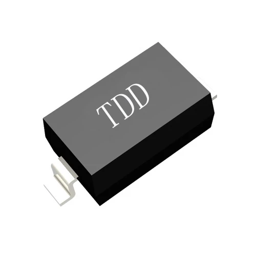
For buyers, the practical question is not simply which circuit is more efficient. It is whether the complete design can deliver stable output, handle startup surges, manage heat, and meet the required service life at an acceptable cost.
Understand what each rectifier returns to the load
Half-wave rectification uses one half of each AC cycle
A half-wave rectifier typically uses one diode in series with the load. It passes one polarity of the AC waveform and blocks the other, so the output consists of separated pulses. The circuit has few components and is easy to assemble, but it makes less effective use of the AC source.
- Typical circuit: one diode and a load, with an optional filter capacitor.
- Ideal average DC output without a filter: approximately 0.318 times the secondary peak voltage.
- Ripple frequency: the same as the AC input frequency.
- Typical use: low-current, cost-sensitive circuits that can tolerate substantial ripple or use additional regulation.
Full-wave rectification uses both halves of each AC cycle
A full-wave circuit converts both halves of the AC waveform into output pulses of the same polarity. It can use a four-diode bridge or two diodes with a center-tapped transformer. Because output pulses arrive more frequently, filtering is generally easier and the DC supply is usually more stable under load.
- Typical circuit: four diodes in a bridge, or two diodes with a center-tapped secondary.
- Ideal average DC output without a filter: approximately 0.637 times the relevant secondary peak voltage.
- Ripple frequency: twice the AC input frequency.
- Typical use: general-purpose DC supplies, equipment with variable loads, and applications where output smoothness matters.
These ideal averages do not equal the final voltage of a practical filtered supply. Diode drops, transformer regulation, capacitor charging, load current, and any downstream regulator all affect the measured output.
Compare the electrical performance before choosing a circuit
Use the core parameter table to narrow the design
The figures below describe ideal or common circuit behavior, not guaranteed product ratings. Actual diode limits must come from the selected component datasheet, and actual output should be confirmed in the finished circuit.
| Parameter | Half-wave rectifier | Full-wave bridge | Full-wave center tap |
|---|
| Diodes conducting per output pulse | 1 | 2 | 1 |
| Ideal average output without filter | 0.318 x secondary peak | 0.637 x secondary peak | 0.637 x half-winding peak |
| Ripple frequency | Input frequency | 2 x input frequency | 2 x input frequency |
| Ideal maximum rectification efficiency | About 40.6 percent | About 81.2 percent | About 81.2 percent |
| Peak inverse voltage per diode | Approximately secondary peak | Approximately full secondary peak | Approximately twice the half-winding peak |
| Transformer requirement | Ordinary secondary winding | Ordinary secondary winding | Center-tapped secondary winding |
| Conduction path voltage loss | One forward drop | Two forward drops | One forward drop |
For the table, secondary peak means the peak voltage across the winding used by the circuit. In a center-tapped design, the voltage for average output is measured from the center tap to one end of the winding. Check the circuit topology carefully before translating these relationships into a diode voltage rating.
Account for ripple, diode loss, and transformer use together
Full-wave rectification usually produces less ripple for the same load and filter capacitance because the capacitor is replenished twice as often. A useful first-order estimate for capacitor-filter ripple is output current divided by ripple frequency times capacitance. This is an approximation; transformer impedance, capacitor ESR, diode conduction angle, and load changes affect the result.
- Half-wave ripple estimate: approximately load current divided by input frequency times capacitance.
- Full-wave ripple estimate: approximately load current divided by twice the input frequency times capacitance.
- Bridge loss: allow for two diode forward drops in the conducting path.
- Center-tap loss: allow for one diode forward drop, but account for the transformer winding and its utilization.
A bridge avoids the need for a center-tapped transformer, but its two conducting diodes create more voltage loss. A center-tap circuit has one conducting diode at a time, but requires the correct transformer and places a higher peak inverse voltage demand on each diode. The best choice depends on the available secondary voltage, current, space, and thermal budget.
Select diode ratings for real operating conditions
Check reverse voltage, average current, and surge current
Do not select a diode by nominal load current alone. A rectifier repeatedly charges the filter capacitor in short pulses, and startup or fault conditions can produce current far above the steady load value.
- Determine the maximum secondary voltage, including high-line conditions and transformer no-load rise.
- Calculate the peak inverse voltage required by the actual topology, then choose a suitable repetitive peak reverse voltage rating with design margin.
- Choose an average forward current rating that covers the load and the way current flows through each diode in the circuit.
- Check non-repetitive surge current for capacitor inrush, power-on events, and likely fault conditions.
- Estimate forward power loss using the diode forward voltage and actual current waveform, then verify junction temperature and heat dissipation.
- Review reverse leakage, operating temperature range, package, mounting method, and any required safety or qualification standards.
Datasheet current ratings are tied to specified lead, case, or ambient temperatures and test conditions. A diode rated for a particular current on paper may require a larger copper area, airflow, or heatsinking to operate reliably in a compact enclosure.
Match recovery behavior and package to the application
For ordinary 50 or 60 Hz mains-frequency rectification, a standard silicon rectifier is often appropriate. Switching power supplies and high-frequency circuits may need a fast-recovery or ultrafast diode because reverse recovery can add switching loss and electrical noise. A Schottky rectifier can reduce forward drop in some low-voltage designs, but its reverse leakage and voltage rating need careful review.
- Choose a through-hole package when mechanical strength, easy prototyping, or heatsinking is important.
- Choose a surface-mount package when board area and automated assembly are priorities, while checking PCB thermal limits.
- Compare the datasheet test conditions, not only the headline current and voltage numbers.
Compare practical operating experience and ownership costs
Full-wave designs usually provide steadier output under changing loads
In practical supplies, a full-wave circuit usually makes better use of a filter capacitor and can reduce low-frequency hum and visible output variation. This can improve the operating stability of sensitive loads, provided the transformer, diodes, capacitor, and regulator are correctly sized. It does not guarantee stable voltage by itself; a rectifier and capacitor are not substitutes for a properly designed voltage regulator.
A half-wave supply may show more pronounced ripple and voltage sag when the load draws current. Increasing capacitance can reduce ripple, but it also increases charging pulses and startup stress on the diode and transformer. Larger capacitors also add cost, board space, and inrush current, so they are not a free fix.
Battery life depends on the complete charger, not the rectifier alone
Neither half-wave nor full-wave rectification directly determines battery life. Battery runtime depends mainly on battery capacity, charging and discharging limits, temperature, load profile, and the quality of the charge-control system. Full-wave rectification can make it easier to create a smoother DC input for a charger, but a rectifier alone does not provide safe charging control.
- Use a suitable constant-current and constant-voltage charging stage where required by the battery chemistry.
- Include overvoltage, overcurrent, temperature, and reverse-polarity protection as appropriate.
- Check ripple and input variation at the charger under minimum and maximum load.
- Measure charging temperature and confirm charge termination behavior in the finished product.
For longer service life, test the complete power path over realistic operating cycles. Record output voltage, ripple, diode temperature, transformer temperature, and behavior at startup rather than relying on a single no-load measurement.
Weigh the advantages and disadvantages before purchasing
Half-wave rectification favors simplicity and low component count
- Advantages: uses one diode, has a straightforward circuit, and can suit very low-power or noncritical loads.
- Disadvantages: uses only one half-cycle, has greater ripple for a given filter setup, and can impose uneven loading on a transformer secondary.
- Best fit: simple indicator or low-current circuits where cost and simplicity matter more than smooth output.
Full-wave rectification favors smoother output and broader use
- Advantages: uses both AC half-cycles, increases ripple frequency, and generally delivers better transformer utilization and easier filtering.
- Disadvantages: a bridge has two diode drops in the conducting path; a center-tap design requires a suitable transformer; either design needs careful thermal and voltage-rating checks.
- Best fit: general DC power supplies and loads that benefit from lower ripple and more consistent operation.
When comparing purchase cost, include more than the diode price. Consider the transformer, filter capacitor, heat management, board area, assembly effort, expected failure risk, and any regulation or protection circuitry needed to meet the product specification.
Choose the rectifier for the application and buyer profile
Use half-wave when the load is forgiving and power demand is low
Half-wave rectification can be suitable for hobby projects, simple sensing circuits, or low-current applications with generous tolerance for ripple. It is also reasonable when a downstream circuit already filters and regulates the supply and the half-wave input has been verified to meet its limits.
Use full-wave when consistency and useful DC output matter
A full-wave bridge is a practical default for many general-purpose supplies when a standard transformer secondary is available and the voltage lost across two diodes is acceptable. A center-tap circuit can be appropriate when the transformer is already designed for it and its voltage, current, and diode reverse-voltage requirements are satisfied.
For purchasing teams, engineers, and product owners, compare samples under the intended load and temperature range before approving a part. Confirm the datasheet, traceability, package compatibility, supply continuity, and quality documentation with the supplier. Shenzhen Daya Electronics Co., Ltd. provides General Rectifier Diode options for engineers and buyers evaluating rectification components; final selection should be based on the circuit specification and verified component data.
Validate the design before production
Follow a repeatable bench-check process
- Confirm the transformer output and polarity with the intended input conditions.
- Measure rectified voltage with no load and at the minimum, typical, and maximum expected load.
- Measure ripple using an appropriate oscilloscope setup and record the test conditions.
- Check diode and transformer temperature after the supply reaches thermal equilibrium.
- Test startup, shutdown, load transients, and any expected abnormal conditions.
- Verify that the regulator or charger remains within its input limits across the full operating range.
A design that passes a brief no-load test may still fail during capacitor inrush, high ambient temperature, or sustained maximum load. Documenting the test setup and results makes supplier comparisons and production checks more reliable.
In short, half-wave rectification offers simplicity, while full-wave rectification generally offers smoother output and better use of the AC cycle. Select a General Rectifier Diode only after checking topology-specific reverse voltage, current, surge, thermal, and recovery requirements, then validate the complete supply under real operating conditions.


