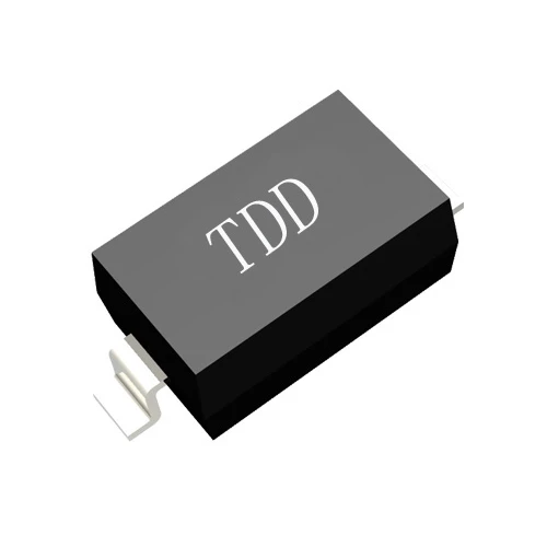
A Solar Bypass Diode helps protect a solar module when shade, dirt, damage, or cell mismatch limits current through part of the module. It can reduce the chance that a weak cell substring overheats, but it does not eliminate every hot-spot risk. Shenzhen Daya Electronics Co., Ltd. works with electronic components for solar applications. The image below accompanies this guide.
1. Understand how a Solar Bypass Diode limits hot-spot risk
How the diode responds to a shaded or weak substring
Solar cells in a module are commonly connected in series within groups called substrings. Series-connected cells carry the same current. If one cell or substring is shaded, dirty, cracked, or electrically weak, it may not be able to carry the current produced by the other cells. The affected area can become reverse biased and dissipate heat. This localized heating is known as a hot spot.
A bypass diode is connected in parallel with a substring, usually inside the module junction box. Under normal operating conditions, it is reverse biased and carries little or no current. If the substring voltage becomes sufficiently negative, the diode becomes forward biased and provides an alternate path for current around that substring.
- The protected substring contributes less or no voltage while it is bypassed.
- The rest of the module can continue producing power, subject to system conditions.
- By reducing current forced through a weak substring, the diode can limit heating and reduce hot-spot risk.
- Bypass operation involves a power loss and is not a repair for damaged cells, poor connections, or persistent shading.
What the diode cannot protect against
A bypass diode is one layer of module protection, not a guarantee against all thermal damage. A failed diode, a loose junction-box connection, severe cell damage, repeated shading, or an incorrectly matched replacement can still create safety and performance problems. Hot-spot resistance also depends on module design, installation conditions, and the cause of the current mismatch.
2. Identify the symptoms and pain points before taking action
What an owner or purchasing team may notice
Purchasers and maintenance teams usually want to know whether a diode can prevent a costly module failure, how to recognize a diode problem, and how to source a compatible component without risking a warranty or creating a safety hazard. Start by recording symptoms and operating conditions rather than assuming the diode is the cause.
- A module or string produces less power than expected.
- Output drops when a particular part of the module is shaded.
- A thermal inspection shows an unusually warm cell area or junction box.
- There are visible signs of cracked cells, discoloration, moisture, scorching, or damaged cables.
- A diode test or qualified service report indicates an open-circuit or short-circuit failure.
Separate diode faults from other causes
Shading from trees, nearby buildings, debris, bird droppings, poor connectors, damaged cells, inverter issues, and string mismatch can produce similar symptoms. Compare module and string performance under similar conditions, review the module manufacturer's documentation, and use a qualified technician for electrical and thermal diagnostics. Do not open a junction box just because output is low.
3. Gather the required tools and safety equipment
Tools for non-invasive inspection and diagnosis
Use the tools appropriate to the inspection. Testing equipment does not make live photovoltaic circuits safe to handle. Solar modules can generate hazardous DC voltage whenever they are illuminated, and series-connected strings can remain energized even after an inverter is turned off.
- Module datasheet, wiring diagram, and manufacturer service instructions.
- Site layout, string map, and inverter monitoring data, if available.
- Digital multimeter rated for the system voltage and measurement category, used only by a trained person.
- DC clamp meter rated for the installation, when current measurement is required.
- Thermal camera or infrared thermometer for a controlled, qualified thermal inspection.
- Insulated tools and appropriately rated personal protective equipment selected by the site's electrical safety plan.
- Lockout and tagout equipment and approved isolation devices, where the site procedure requires them.
- Camera, labels, and inspection log for recording the module identification and findings.
When not to proceed
Stop and refer the work to a qualified solar or electrical technician if the module is cracked, the junction box is burned or wet, wiring is damaged, the isolation status is uncertain, or the required test equipment and training are unavailable. Do not disconnect connectors under load, short a module to test it, or rely on gloves alone as protection.
4. Follow a step-by-step inspection and troubleshooting process
Step 1: Review module and system information
Record the module make, model, serial number, rated electrical characteristics, number of substrings, and junction-box configuration. Check the manufacturer's instructions for the number and type of bypass diodes and any approved test or service procedure. Confirm whether field diode replacement is permitted or whether the module must be returned or replaced.
Step 2: Record the reported problem
Note when the power loss occurs, which modules or strings are affected, recent weather, shading patterns, cleaning history, and any inverter alarms. Compare monitoring data for similar strings and operating conditions. This helps distinguish a persistent electrical fault from temporary shade or soiling.
Step 3: Carry out a visual inspection from a safe position
Look for shade, accumulated dirt, leaves, bird droppings, cracked glass, frame damage, cable strain, loose-looking connectors, and visible junction-box damage. Do not touch exposed conductors or open the junction box. Photograph and document any abnormal condition.
Step 4: Arrange qualified electrical isolation
Before electrical testing or service, have a qualified person follow the site-specific isolation and lockout procedure and verify the circuit condition with equipment rated for the installation. Follow the module, inverter, and local electrical safety instructions. Remember that an illuminated module can remain a source of DC power even when other equipment is switched off.
Step 5: Test only by an approved method
A trained technician should use the manufacturer's procedure to evaluate module output, string behavior, and, when permitted, diode function. Diode mode on a multimeter may help identify some open or shorted diodes after the diode has been safely isolated from the circuit. In-circuit readings can be misleading because other electrical paths affect the measurement. Do not guess at test thresholds or probe a live junction box.
Step 6: Compare findings with the module specification
Check measured results against the datasheet, environmental conditions, and the manufacturer's acceptance limits. A single reading is not enough to confirm a fault if irradiance, temperature, shade, or measurement setup differs from the stated test conditions. Have a qualified technician interpret any abnormal results.
Step 7: Decide on repair, replacement, or further investigation
If testing indicates a diode fault, follow the manufacturer's approved remedy. Depending on the module design and warranty, the correct response may be professional junction-box service, module replacement, or a manufacturer return. After any approved repair, the technician should verify the enclosure, seals, wiring, electrical performance, and safe operation before the module returns to service.
5. Select a compatible replacement diode and supplier
Check the electrical and physical specifications
Do not select a diode based only on appearance or a similar part number. Confirm each requirement against the module maker's design and documentation.
- Diode type and intended function in the module circuit.
- Rated forward current and surge current appropriate to the application.
- Reverse voltage rating with adequate margin for the module design.
- Forward voltage, power dissipation, and thermal performance.
- Package, mounting method, lead configuration, and junction-box fit.
- Operating temperature range and environmental suitability.
- Required certifications, traceability, and supplier quality documentation.
- Compatibility with the original circuit, module warranty, and approved service method.
Questions for purchasing and engineering teams
Before placing an order, ask the supplier and module manufacturer to confirm the part's suitability for the exact module or junction-box design. Request current datasheets, lot traceability, quality and compliance information, and guidance on approved installation. Shenzhen Daya Electronics Co., Ltd. can be included in a sourcing discussion when evaluating electronic components, but final selection must be based on verified technical compatibility and the module manufacturer's requirements.
6. Avoid common inspection, testing, and replacement mistakes
Mistakes that can create safety or reliability problems
- Assuming that a bypass diode prevents every hot spot or makes persistent shade harmless.
- Replacing a diode without confirming the original specification and module design.
- Opening a junction box or probing conductors while the module or string may be energized.
- Disconnecting connectors under load or shorting a module as a test method.
- Using an unrated meter, incorrect meter setting, or improvised test leads.
- Diagnosing a diode fault from low output alone without checking shade, soiling, connectors, cells, and inverter data.
- Ignoring enclosure seals, moisture protection, strain relief, polarity, or thermal management during an approved repair.
- Making an unauthorized modification that can void a product warranty or compromise module safety certification.
Use a documented closeout check
Keep the module identification, inspection photographs, test equipment details, environmental conditions, service approval, replacement part data, and final test results with the maintenance record. A clear record helps purchasing and engineering teams identify repeat failures and supports future warranty or supplier discussions.
7. Use the findings to reduce future hot-spot risk
Preventive actions for owners and project teams
Plan the array to avoid recurring shade, keep modules clean according to the manufacturer's recommendations, inspect wiring and junction boxes during scheduled maintenance, and review performance data for persistent string or module differences. Use thermal inspections only under suitable conditions and have results interpreted by trained personnel. When a module repeatedly activates a bypass diode, investigate and address the underlying shade, damage, or mismatch rather than treating diode operation as a permanent fix.
Make the next purchasing decision evidence-based
Use field data and the module manufacturer's guidance to decide whether a replacement diode, junction box, or complete module is appropriate. Verify the specifications, supplier documentation, warranty terms, and approved repair method before ordering. A correctly selected Solar Bypass Diode can help route current around a weak substring and limit hot-spot risk, while safe diagnosis and compatible components protect the reliability of the full module. Shenzhen Daya Electronics Co., Ltd. can support component sourcing discussions, and every Solar Bypass Diode selection should be confirmed against the module manufacturer's requirements.


