Small Signal Schottky Diode leakage can rise sharply as junction temperature increases, affecting standby current, battery life, circuit bias, and reliability. The actual change depends on the part, reverse voltage, package, and test conditions. This guide explains how to read leakage specifications, measure temperature effects, and compare parts using repeatable steps.
For purchasing teams, the key question is not simply whether a diode has low leakage at room temperature. It is whether leakage remains acceptable across the full operating range and under the actual reverse voltage in the design. Shenzhen Daya Electronics Co., Ltd. provides product information to support component evaluation. Review the exact part datasheet and confirm limits with the supplier before approving a design.
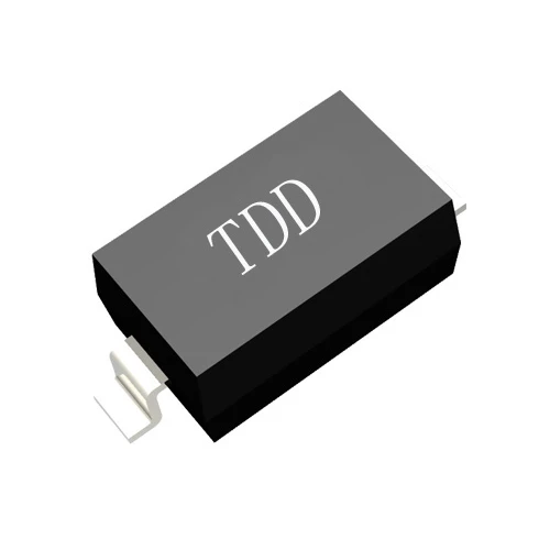
Temperature usually increases reverse leakage.
Understand the leakage mechanism.
A Schottky diode uses a metal-semiconductor junction. When reverse biased, a small current can flow even though the diode is not intended to conduct in the forward direction. As junction temperature rises, more charge carriers have enough energy to contribute to current across the junction. Consequently, reverse leakage commonly increases with temperature and may rise much faster than a simple linear estimate suggests.
The exact relationship is device-specific. Do not apply one universal temperature multiplier to every Small Signal Schottky Diode. Leakage also depends on reverse voltage, manufacturing process, die area, package, and the condition of the device. Use the manufacturer's typical curves for trends and maximum ratings for design limits.
Separate reverse leakage from forward current.
- Reverse leakage is measured with the cathode at a higher potential than the anode, within the specified reverse-voltage range.
- Forward current is measured with the diode conducting in the forward direction. Its voltage drop and current behavior also vary with temperature, but they are not the same specification as reverse leakage.
- Leakage measured on a complete circuit may include current through the PCB, contamination, connectors, protection devices, and test equipment. It may not all come from the diode.
Datasheet conditions determine what a leakage number means.
Check the complete specification.
Before comparing parts, record the conditions attached to the reverse-current specification. A value measured at one reverse voltage and one temperature cannot be directly compared with a value measured under different conditions.
- Maximum reverse leakage current and whether the value is a guaranteed limit or a typical value.
- Reverse test voltage used for the leakage measurement.
- Temperature at which the specification or curve applies.
- Operating junction-temperature range and maximum junction temperature.
- Package type, power rating, and any relevant thermal resistance information.
- Test method, sample conditions, and revision date of the datasheet.
Read curves without over-interpreting them.
Typical curves help estimate how leakage trends with reverse voltage or temperature, but they do not usually guarantee the behavior of every production unit. Treat a maximum rating as a boundary under its stated conditions, not as a prediction of typical performance. If the datasheet does not provide a leakage curve at the temperatures important to the design, request clarification or test representative samples.
Measure leakage with a controlled test setup.
Gather the required tools.
- A source measure unit, or a low-leakage voltage source and a sensitive ammeter, capable of measuring the expected current.
- A temperature chamber or controlled thermal fixture that covers the intended test temperatures.
- A calibrated temperature sensor placed near the device, with a suitable method to estimate or verify device temperature.
- A clean, low-leakage test fixture, short leads, and suitable guarding or shielding for very small currents.
- A stable power source, current compliance setting, and the correct reverse-bias connections.
- A computer or log sheet to record temperature, reverse voltage, leakage, stabilization time, device identifier, and instrument settings.
- Appropriate handling equipment and protection against electrostatic discharge.
Follow these measurement steps.
- Define the test conditions. Set the reverse voltage, temperature points, settling time, and acceptance limit from the product datasheet and circuit requirements. Never exceed the diode's ratings.
- Inspect and clean the setup. Check the diode, fixture, connectors, and PCB for residue, moisture, dust, or damage. Surface contamination can create a leakage path that is comparable to the device current.
- Connect the diode in reverse bias. Verify anode and cathode orientation before applying voltage. Set current compliance to protect the device and fixture if a wiring error occurs.
- Verify the instruments at the expected current range. Confirm meter range, zero behavior, cable leakage, and instrument connection. Use a blank-fixture check when the expected diode leakage is very small.
- Set the first temperature point. Allow the fixture and device to reach thermal equilibrium. Do not assume that chamber air temperature equals junction temperature immediately after a temperature change.
- Apply the specified reverse voltage gradually. Allow the reading to settle and record leakage, temperature, voltage, instrument range, and elapsed stabilization time.
- Repeat at each planned temperature. Use the same reverse voltage, connection method, and settling criteria at every point so that the readings can be compared fairly.
- Repeat measurements when needed. Test multiple samples and repeat readings to identify unstable contacts, outliers, or measurement drift. Keep individual sample results rather than recording only an average.
- Compare results with the requirement. Check the highest measured leakage against the circuit's worst-case allowance and the supplier's guaranteed limits. Include measurement uncertainty and operating margin.
- Document and review the test. Save the setup, calibration status, sample identification, environmental conditions, raw readings, and pass or fail rationale for future supplier and design reviews.
Interpret temperature data against the real circuit.
Check the worst-case operating point.
Identify the maximum expected junction temperature and reverse voltage in the application, not only the room-temperature bench condition. In a battery-powered circuit, even a small leakage increase may shorten standby life. In a high-impedance signal path, leakage may shift a bias point or cause measurement error. In a protection or switching circuit, leakage may increase unwanted current during an off state.
Estimate total circuit leakage by including all parallel paths. Add the diode contribution to leakage from other components, PCB surfaces, connectors, and measurement interfaces. Then compare the total with the allowed standby current, bias error, or signal accuracy requirement.
Use a consistent comparison method.
- Compare candidate devices at the same reverse voltage and temperature.
- Use guaranteed maximum values for worst-case design checks and typical values only for planning or trend comparisons.
- Compare data from the same test method where possible. Different fixtures and instruments can produce different readings near the measurement floor.
- Check whether the desired temperature is within the rated operating range and whether the datasheet provides a guaranteed leakage limit there.
- Allow for part-to-part variation, measurement uncertainty, aging requirements, and the application's required design margin.
Select a diode based on application risk.
Use this purchasing checklist.
- Write down electrical needs. Specify maximum reverse voltage, forward current, acceptable forward voltage, maximum reverse leakage, and signal-frequency needs.
- Define the temperature range. Include storage, operating, and expected board temperatures. Identify the worst-case junction temperature rather than relying only on room temperature.
- Set a leakage budget. Decide how much current the diode can consume without affecting battery life, bias accuracy, or circuit operation.
- Screen datasheets. Confirm package, ratings, leakage test conditions, temperature data, and guaranteed limits. Ask the supplier when essential conditions are missing.
- Evaluate samples under application conditions. Test representative parts at the relevant reverse voltage and temperature using a controlled, documented method.
- Review supply and traceability needs. Confirm ordering information, manufacturing status, quality documentation, and change-notification expectations with the supplier.
- Approve with margin. Select a part that meets the leakage budget across the required range, with allowance for unit variation and measurement uncertainty.
Balance leakage against other requirements.
A lower-leakage candidate may have a different forward voltage, capacitance, package, or cost. Choose according to the complete circuit requirement rather than optimizing one datasheet number in isolation. For signal switching, also check whether capacitance and switching behavior affect signal integrity. For low-power designs, verify leakage at the highest credible temperature and the actual off-state voltage.
Reduce leakage impact with practical design choices.
Improve the board and measurement environment.
- Keep high-impedance leakage nodes clean and dry, and select a PCB cleaning process compatible with the assembly.
- Use suitable spacing and guarding where very small currents are measured or where high-impedance nodes are exposed to contamination.
- Keep the diode away from unnecessary heat sources when layout and thermal requirements allow.
- Use a reverse voltage no higher than the application requires while preserving adequate circuit margin.
- Choose a device whose guaranteed leakage fits the system budget instead of assuming software or calibration will remove an unstable current.
Verify the complete assembly.
After selecting a device, measure the assembled circuit at representative temperature and voltage conditions. Board-level leakage can differ from a diode-only measurement because solder flux, coating, humidity, and nearby components create additional paths. Record both component-level and system-level results so that a failure can be traced to the correct source.
Avoid common leakage measurement mistakes.
Check these errors before trusting a result.
- Comparing mismatched test conditions. A leakage value at a lower reverse voltage or temperature is not a valid substitute for the required worst-case condition.
- Using a meter that cannot resolve the current. A basic multimeter may not have adequate sensitivity or may add enough burden voltage to distort a low-current measurement.
- Skipping thermal stabilization. Logging chamber air temperature before the device has settled can associate a reading with the wrong device temperature.
- Ignoring fixture leakage. Contamination, humid surfaces, cables, and connectors can make an ordinary fixture appear to show diode leakage.
- Reversing the diode connections. Incorrect polarity can create forward conduction or damage the device and invalidate the test.
- Exceeding the specified reverse voltage. Overstress can permanently change the device or cause failure. Stay within ratings and use current compliance.
- Treating typical curves as guaranteed limits. Typical data describes expected behavior, not necessarily the maximum value for every unit.
- Testing only one sample. A single device cannot establish production variation or provide a robust purchasing decision.
- Ignoring the assembled board. A diode that passes alone may still fail the system leakage budget because of PCB or component-level paths.
Make the decision with documented evidence.
Turn test results into an approval record.
A useful evaluation record includes the part number and datasheet revision, sample identifiers, test equipment and calibration status, reverse voltage, temperature, settling time, raw leakage readings, measurement uncertainty, and acceptance limit. Add the circuit's leakage budget and explain how the measured results support the design decision. This gives engineering and purchasing teams a consistent basis for comparing suppliers and resolving questions.
Temperature can make reverse leakage a critical selection factor, especially in low-power and high-impedance circuits. Read specifications under their stated conditions, test with a controlled setup, and verify the complete assembly across the intended operating range. Shenzhen Daya Electronics Co., Ltd. can be contacted for product information and part evaluation support. Use these checks to select a Small Signal Schottky Diode that meets the real application requirement.


