Choosing a Schottky Barrier Rectifier for a DC power rail is not just a matter of matching the load current to a number on a datasheet. The rectifier must withstand the rail voltage and transients, stay within its junction temperature limit, and meet efficiency, leakage, footprint, and supply requirements. This guide provides a step-by-step sizing method for engineers and purchasing teams. Shenzhen Daya Electronics Co., Ltd. supports component selection for power applications. The image below introduces the product category.
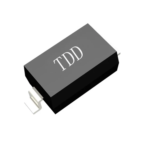
Start with the rail conditions and rectifier role
Identify how the diode is used
First determine whether the diode is used for input reverse-polarity protection, output OR-ing, a freewheel path, a clamp, or rectification. Its position in the circuit determines which current waveform, reverse voltage, and transient conditions matter. A diode in series with a rail may carry nearly the full load current, while an OR-ing diode may conduct only when its source is supplying the load.
Record the electrical and environmental requirements
Before comparing parts, document the operating conditions that affect selection:
- Nominal rail voltage and the highest normal voltage, including supply tolerance.
- Maximum continuous load current and the expected load-current waveform.
- Startup, hot-plug, motor, capacitor-charging, and other short-duration current peaks.
- Possible reverse voltage and the source and duration of voltage transients.
- Ambient temperature, enclosure conditions, airflow, PCB copper area, and nearby heat sources.
- Allowed forward voltage drop, power loss, standby current, and thermal rise.
- Required package, footprint, qualification level, production quantity, and expected product life.
Separate measured or specified conditions from assumptions. If a transient, temperature, or load value is unknown, identify how it will be measured or bounded before approving a part.
Gather the tools and datasheet information
Prepare the tools before calculating
The following tools help turn the circuit requirements into a realistic selection and then confirm that the design works:
- The circuit schematic, rail specifications, and load profile.
- Candidate manufacturer datasheets and a spreadsheet or calculator for loss and temperature estimates.
- A programmable DC supply and electronic load for steady-state and load-step testing.
- A digital multimeter for checking rail voltage, forward drop, and continuity.
- An oscilloscope with suitable probes for startup, switching, and transient measurements. Use a differential probe when the measurement point is not safely referenced to ground.
- A current probe or a correctly rated, low-inductance shunt for capturing current peaks and waveforms.
- A thermocouple or thermal camera for checking component and board temperature during sustained operation.
- The intended PCB layout or a representative test board, since thermal performance depends on mounting and copper area.
Collect comparable datasheet parameters
Check each candidate under the same conditions. Record the maximum repetitive reverse voltage, average forward current and its specified test conditions, forward voltage versus current and temperature, reverse leakage at relevant reverse voltage and temperature, surge-current rating and pulse conditions, maximum junction temperature, thermal resistance, package, and assembly requirements. A headline current rating alone is not enough to establish suitability.
Follow these steps to size the rectifier
Step 1: Find the maximum reverse voltage
Determine the greatest reverse voltage that can appear across the diode in normal operation, including the highest source voltage, tolerances, startup behavior, and circuit states. Add credible transients based on the actual system environment and protection design. Select a repetitive reverse-voltage rating, often listed as VRRM, that exceeds the calculated worst-case voltage with a deliberate design margin. Do not rely on a generic margin without checking the transient source and the manufacturer's recommendations.
Step 2: Establish the diode current waveform
Trace when the diode conducts and measure or calculate its current. For a series protection diode, this may be the rail load current. For a switching or freewheel position, current may be pulsed and depend on duty cycle and operating mode. Record average current, peak current, pulse duration, repetition rate, and startup or fault current separately. Do not treat a short surge rating as permission to exceed the continuous rating in normal operation.
Step 3: Estimate forward conduction loss
Use the forward-voltage curve at the expected current and junction temperature rather than relying only on a typical value at a different test point. For a nearly constant current, a first estimate is P equals IF times VF. For a varying waveform, estimate average loss from the time average of forward voltage multiplied by forward current over the conduction interval. Include duty cycle and operating modes. Recalculate using a conservative forward-voltage value because VF varies between parts and with current and temperature.
Step 4: Check reverse leakage and standby loss
Read reverse leakage at the maximum expected reverse voltage and at an appropriate high temperature. Leakage can rise substantially with temperature and can matter in battery-powered products, standby rails, or high-impedance circuits. Estimate standby loss as reverse voltage multiplied by reverse leakage when that is the relevant operating condition. Confirm that leakage will not discharge a battery, disturb a sensing circuit, or exceed the system's standby-power budget.
Step 5: Check surge and fault conditions
Compare startup and fault pulses with the candidate's surge-current specifications. Check the datasheet pulse duration, waveform, starting junction temperature, and repetition limits; ratings are not interchangeable between conditions. If a fuse, current limiter, or upstream protection is expected to clear a fault, verify its clearing time against the rectifier's pulse capability.
Step 6: Verify junction temperature
Estimate junction temperature using the calculated total power and a thermal path that matches the real mounting. For an initial board-level estimate, junction temperature is approximately ambient temperature plus power multiplied by junction-to-ambient thermal resistance. For a case-mounted or heatsink design, include junction-to-case, interface, and heatsink thermal resistance as applicable. Use the correct datasheet thermal conditions and PCB copper assumptions. Keep the predicted junction temperature below the maximum rating with a margin suitable for the product's reliability target.
Step 7: Compare candidates and confirm the design
Shortlist parts that meet voltage, current, surge, leakage, temperature, package, and layout requirements. Compare forward loss at the actual operating point, not just the lowest listed VF. Then test the leading candidate on the intended board at maximum load and worst-case ambient conditions. Recheck the selection if the measured temperature, drop, or transient response differs materially from the estimate.
Check thermal performance in the real assembly
Use the correct thermal conditions
Thermal resistance values depend on package, copper area, board thickness, airflow, and test setup. A junction-to-ambient figure from a datasheet may not represent a compact production board. Use the manufacturer's layout notes and thermal data that best match the actual PCB. If the calculated temperature is close to the limit, improve the copper and thermal path or select a lower-loss or larger-package device rather than assuming the board will cool it sufficiently.
Test sustained load and worst-case operation
Run the board until temperatures stabilize at the highest expected ambient and load. Measure the case or accessible package surface and use the manufacturer's guidance to relate that measurement to junction temperature. Test startup and load changes separately because short peaks may create electrical stress even when average temperature is acceptable. Record the board revision, airflow, load, ambient temperature, and measurement location so the results can be reproduced.
Compare parts using electrical and purchasing criteria
Use a side-by-side selection checklist
Compare candidate Schottky Barrier Rectifier parts against the same requirements:
- Voltage rating: adequate for maximum reverse voltage and credible transients.
- Current capability: suitable under the datasheet's mounting and temperature conditions.
- Forward drop: low enough at the real current to meet efficiency and temperature targets.
- Reverse leakage: acceptable at the expected reverse voltage and elevated temperature.
- Surge capability: suitable for the measured pulse shape, duration, and repetition.
- Thermal path: compatible with the PCB footprint, copper area, airflow, and enclosure.
- Package and assembly: compatible with the production footprint, solder process, and inspection method.
- Supply risk: confirm manufacturer, authorized supply route, lead time, lifecycle status, and production availability.
- Substitution rules: verify that any alternate has compatible pinout, package, ratings, and thermal behavior.
Resolve purchasing questions before release
Purchasing teams need more than a part number and target price. Confirm the exact manufacturer part number, approved source, packaging, minimum order quantity, lead time, traceability, and change-notification expectations. Ask engineering to approve alternates against written electrical and mechanical limits. A lower-cost substitute can create extra validation work or field risk if its leakage, package, pinout, or thermal performance differs from the qualified part.
Avoid these common sizing mistakes
Do not select by current rating alone
Current ratings depend on specified test conditions and do not automatically guarantee safe operation on a small PCB. Check the actual current waveform, forward loss, mounting conditions, and junction temperature together.
Do not ignore high-temperature leakage
Typical leakage at room temperature may understate standby loss in a hot enclosure. Use the relevant maximum datasheet value and verify the system impact at the highest expected temperature.
Do not confuse surge rating with continuous capability
A surge-current rating applies only to specified pulse conditions. Check pulse duration, waveform, initial temperature, and repetition rate before using it to justify a startup or fault condition.
Do not overlook transients or assume ideal voltage
Nominal rail voltage does not describe hot-plug events, inductive loads, supply overshoot, or wiring transients. Measure or calculate credible peaks and coordinate the diode rating with the system's clamping and protection components.
Do not assume parallel diodes share current evenly
Forward-voltage differences and thermal behavior can cause uneven sharing. Use parallel devices only with a design that addresses current balance and thermal coupling, and verify sharing over production and temperature variation.
Do not approve an alternate by package name alone
Parts in similar-looking packages can have different pinouts, footprints, thermal performance, leakage, and ratings. Compare the complete datasheets and validate the alternate in the intended circuit before release.
Use a final release checklist
Document the decision and test evidence
Before releasing the design or purchase specification, confirm and record each item:
- The diode's circuit role and worst-case operating modes are documented.
- Maximum reverse voltage, transients, and the selected voltage margin are reviewed.
- Continuous, peak, surge, and waveform-dependent current conditions are checked.
- Forward loss and high-temperature reverse leakage meet system budgets.
- Junction-temperature estimates use realistic board and ambient conditions.
- Prototype tests cover maximum load, startup, relevant transients, and thermal stabilization.
- The exact part number, package, approved source, and alternate approval rules are recorded.
A well-sized Schottky Barrier Rectifier is selected from the complete electrical, thermal, layout, and sourcing picture, then confirmed under real operating conditions. Following these checks helps reduce power loss, prevent overstress, and avoid costly component substitutions later.


